This article was originally published on Cycle World.
Single-shock rear suspensions are near-universal today. Traditional twin-shock setups are still seen, but exist mainly for reasons of retro style. When the era of longer rear-suspension travel arrived in 1974, it made the best sense to implement it with a single-suspension unit.
Why have suspension at all? For decades, American motorcycles had rigid frames—no rear suspension. But as highways improved and speeds rose, rear suspension became necessary to provide chassis stability. Letting just the sprung wheel ride up and down over bumps saved the rider and chassis from their disturbance.
The rear shock provides two basic functions: Supporting the weight of the rear of the bike with a bump-softening spring, and controlling any up-and-down oscillations of the suspension by providing damping. Damping is a controlled friction force that drains energy out of unwanted suspension motions, such as the bouncing that would otherwise continue after every bump.
In the early days, dampers worked by dry friction, but their stick-slip motion was jerky. Modern dampers are smoothly supple because they consist of an oil-filled cylinder and movable piston linked to the suspension. The suspension motion drives the piston, which pumps oil back and forth through restrictive orifices. This converts the energy of suspension motion into the energy of fast-moving jets of damping fluid—energy dissipated as heat. The warmth of a rear shock in use is the energy taken from suspension movement.
As the damper piston moves, pressure ahead of it is high but the low pressure behind it can pull the damper oil apart, or cavitate it. To prevent impacts as cavitated regions collapse, damper oil is pressurized by gas behind an accumulator piston—whose cylinder is the “pistol grip” of today’s most common damper design.
RELATED: What every rider needs to know about their motorcycle carburetor
A simple fixed damping orifice, sized to be workable at low speed, quickly becomes harsh or even rigid as road speed and damper-piston velocity increase. This is because the pressure required to push fluid through a fixed orifice rises as the square of speed. What this means is that if a given orifice provides appropriate damping at a 3-mph walking pace, at double that speed, damping force will be four times greater, and at 60 mph, the damper would become rigid. This steep increase in damping force is called “orifice limitation.”

To avoid orifice limitation, variable orifices were invented, orifices which became larger as the pressure across them increased. One simple approach was to drill a number of holes through the damper piston, cover them with a thin washer, and back that washer with a spring. As the piston moved faster through the fluid, rising fluid pressure would lift the washer more and more against its spring, slowing the rate at which damping force increased with piston velocity. Variable orifices allowed damping force to be kept roughly proportional to piston velocity.
The most often-used scheme today uses the steel washer itself—covering holes through the piston or valve body—as the spring. It is clamped at its ID or OD, and the pressure of fluid driven by the damper’s piston deflects the washer into a slightly conical shape, allowing the flow to emerge from under the washer’s free edge. By stacking sequences of other washers and spacers onto this washer, a wide variety of curves of damping-force-to-velocity can be created. This is the all-important washer stack, also sometimes called a shim stack, so often referred to in suspension setup.
Damping force must be set in proportion to shock-spring stiffness. Otherwise, a stiff spring overpowers weak damping or vice-versa.
The two directions of suspension movement are: compression, as a bump lifts a wheel, and rebound occurring as suspension extends after the bump. For many years, dampers provided almost no damping force on compression because an orifice-limited compression valve could so easily kick a bike upward on hitting a bump, reducing tire grip as the bump passed. When engineers learned to “plateau” compression damping after 1978, it became less upsetting and actually useful.

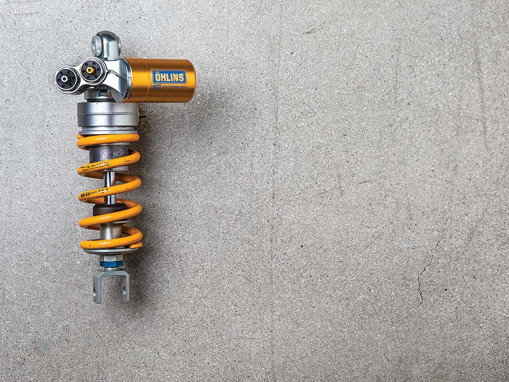
For many years the rebound washer stack was located on the damper piston while the compression stack controlled flow into the accumulator—which used to be mounted remotely, at the end of a flexible hose. The flow controlling compression was just the small fluid volume displaced by the damper rod as it entered the cylinder. Today it is usual for the piston to be solid and to push nearly equal compression and rebound fluid volumes back and forth through washer stacks mounted outside the cylinder (as with this Öhlins TTX shock pictured), making adjustment and service easier. Over time, the flow passages through the damping elements have become ever-more streamlined.
The damping adjusters we call “clickers” typically adjust only low-speed damping; when we say “low-speed” this refers to how fast the shock is being compressed or extended, not the speed of the motorcycle. Altering damping at higher speeds requires altering the washer stacks.
Because damping slows suspension movement, it is a compromise: enough to suppress suspension oscillations but interfering as little as possible with wheel movement.