
The next time you need to crunch a couple of numbers, resist the urge to grab a digital calculator. Instead, round up some variable resistors, also known as potentiometers, and wire them into an analog mathematics rig. By twisting the potentiometers’ knobs and measuring the resulting voltage or resistance with a digital multimeter, you can perform simple multiplication and addition without a microprocessor in sight.
MATERIALS:
- Digital multimeter
- Three 1K-ohm linear potentiometers
- 10K-ohm linear potentiometer
- LM7810 voltage regulator
- 0.33µF electrolytic capacitor
- 0.1µF electrolytic capacitor
- SPST on/off toggle switch
- Four 25/32-by-15/32-inch knobs
- Red binding post
- Black binding post
- Banana-to-banana cables
- Two 9-volt batteries
- Two 9-volt-battery holders
- 5.5-by-8.66-inch project box
- Roll of 22-gauge hookup wire
TOOLS:
- Wire cutters
- Soldering iron
- Screwdriver
- Power drill
- 5/16-inch drill bit

INSTRUCTIONS:
- Follow our schematic diagram for building a 10-volt power supply from the 7810 voltage regulator.
- Wire the two 9-volt-battery holders together in series by soldering a black wire from one holder to the other holder’s red wire.
- Drill holes for the potentiometers and binding posts; you can use our schematic diagram’s drilling template as a guide.
- Solder the remaining red wire from the joined battery holders to the red (+) binding post on the switch.
- Solder the remaining black wire to the black (-) binding post on the switch.
- Solder two 1K-ohm linear potentiometers in series to create a circuit that will help you perform simple addition.
- Solder one 1K-ohm linear potentiometer and the 10K-ohm linear potentiometer together as voltage dividers to make a multiplication circuit.
- Wire the power supply to the voltage-divider potentiometers according to our schematic diagram. Use the binding posts for collecting the black (-) and red (+) wires together.
- Join the series potentiometers and the voltage-divider potentiometers to the respective multimeter inputs. The voltage dividers, used for multiplication, will connect to the multimeter via the binding posts and the banana-to-banana cables. The series potentiometers, used for addition, are soldered to the multimeter’s two probes. Prepare the probes by snipping them off and soldering each remaining wire to one end of the potentiometer series.
- Place the potentiometers and power supply inside the project box.
- Secure the knobs to each of the potentiometer’s shafts.
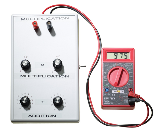
- Mark the range of each addition circuit’s knobs from 1 through 10 in a clockwise direction. Next, mark the range of the multiplication circuit’s knobs from 1 through 0 in a clockwise direction. (See the photo above for guidance.)
- Switch the multimeter’s ohmmeter to 2,000 ohms for addition, and calculate sums using the series potentiometers’ knobs. For multiplication, use the multimeter’s voltmeter (set to 20 DC volts) and measure the product of the voltage-divider potentiometers’ knobs.
OPERATION:
Two modes are used on the multimeter. The ohmmeter displays the series potentiometers’ sums, and the voltmeter displays the voltage-divider potentiometers’ products.
Addition:
Set up the multimeter for addition calculations by connecting the red probe wire to the VΩmA (+) input and the black probe wire to the COM (-) input on the multimeter. Turn on the multimeter and set its selector dial to its ohmmeter function with a setting range of 2,000 ohms. Rotate each knob on the addition potentiometers, and watch the sum on the multimeter display.
Multiplication:
Set up the multimeter for multiplication by connecting the red banana-to-banana cable to the VΩmA (+) input and the black banana-to-banana cable to the COM (-) input on the multimeter. Plug the other end of each cable into the matching-color binding post. Turn on the multimeter, move its selector dial to the voltmeter function, and set the range to 20 volts. Turn on the SPST switch. (Note: This switch sends 10 volts of DC power through the voltage-divider potentiometers.) Turn each multiplication potentiometer and see the product on the multimeter display.
Notes:
There are two noteworthy features about the multiplication function of the analog calculator:
The products are decimal fractions. This is because the potentiometers act as voltage dividers. For example, the first potentiometer divides the reference voltage (i.e., 10 volts DC) in half, which is equivalent to multiplying the reference voltage by 0.5. Similarly, the second potentiometer multiplies the first product by 0.5. Therefore, if each potentiometer is placed at its halfway point, the multimeter will display a product of 2.50, or ((10 * 0.5) * 0.5) = 2.50.
The second feature of the analog calculator’s multiplication function is the presence of an obvious calculator error. Can you spot it? As the two 9-volt batteries begin to lose power, the resulting products will be lower than you would expect to see. For example, with both potentiometers set to 1, the anticipated multimeter display would be 10 volts. As the batteries age, however, the multimeter might display 9.55 volts with both potentiometers set to 1. Therefore, our calculation would be: ((9.55 * .5) * .5) = 2.39.
This article originally appeared in the August 2014 issue of Popular Science.