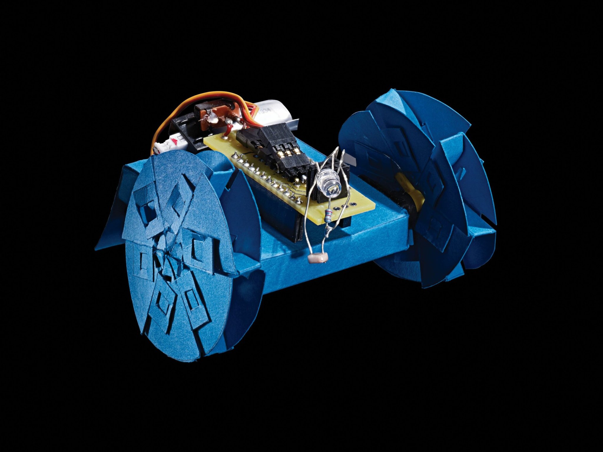
Origami, the ancient art of paper folding, also shows up in modern science and engineering. By turning a two-dimensional sheet into a 3-D product, as origami artists do, engineers can make more-versatile versions of devices like space mirrors and heart stents. The same techniques can also be used to create inexpensive robots.
To get started, simply print out a template, cut, and fold. Once you add some basic electronics, an Arduino brain will command the robot to roll over the floor, sticking to dark surfaces, based on the amount of reflected light it detects. If the robot’s body tears, it’s no big deal. Cardstock costs only about 10 to 30 cents per piece—just print another.
Ankur Mehta, who was an MIT postdoctoral fellow when he designed this machine, says his goal is to get robots into anyone’s hands for cheap. “People who are not engineers should be just as comfortable with creating and using robots as they are interacting with cellphones and smart devices,” he says.
WARNING: Lithium-polymer batteries are a fire hazard. Read the warnings on your battery before plugging it into your paper project.
Stats
- Time: 5 hours
- Cost: $55
- Difficulty: Hard
Tools
- Printer
- X-Acto knife
- Straight edge
- Soldering iron
Materials
- Custom daughter board
- Three sheets 8.5-by-11-inch cardstock
{!! $img_subtitle !!}
Electronic components for the paper robot
This article was originally published in the November 2015 issue of Popular Science, under the title “Fold a Paper Robot.”
Instructions
{!! $img_subtitle !!}
Order a custom daughter board from a printed circuit-board service such as OSH Park. The circuit diagram shows what it will look like, but the manufacturer will also need these .grb files.
{!! $img_subtitle !!}
Print the body and wheel patterns from these folding guides onto cardstock.
{!! $img_subtitle !!}
Print the body and wheel patterns from these folding guides onto cardstock.
{!! $img_subtitle !!}
Carefully cut along the red lines, using the straight edge to guide the knife.
{!! $img_subtitle !!}
Cut the outline first; wait to cut the details until after you’ve made the major folds.
{!! $img_subtitle !!}
Make mountain-folds along blue lines and valley-folds along green ones.
{!! $img_subtitle !!}
Once you’ve made the major folds, carefully cut the details along the red lines.
{!! $img_subtitle !!}
Assemble the wheels.
{!! $img_subtitle !!}
Slide both arms of a plastic servo double-arm into two opposite cutouts at the center of each wheel.
{!! $img_subtitle !!}
On the Arduino, solder six male single pins into the programming header at board top.
{!! $img_subtitle !!}
Solder 12 single male headers along each side on board bottom.
{!! $img_subtitle !!}
Solder battery-connector wires into the (+) and (-) holes on board top.
{!! $img_subtitle !!}
Solder three right-angle male headers into rows 9 and 6 on daughter-board bottom and six female headers into its ANLG holes (this is where the LED, light sensor, and resistor will fit).
{!! $img_subtitle !!}
Solder one end of the resistor to the light sensor.
{!! $img_subtitle !!}
Connect resistor and light sensor to the frontmost three female headers. Connect the LED to two female headers. Solder the switch to board bottom.
{!! $img_subtitle !!}
Solder 12 single female headers along each side of the board top.
{!! $img_subtitle !!}
Now the electronic components are ready to fit into the origami frame.
{!! $img_subtitle !!}
Place the Arduino in the second largest paper segment.
{!! $img_subtitle !!}
Place the Arduino in the second largest paper segment.
{!! $img_subtitle !!}
Make sure the pins go through the holes.
{!! $img_subtitle !!}
Slide tabs of the two smallest servo paper segments into slots on the Arduino paper segment. Place the rectangular parts of the servos into their segments so their shafts are sticking out through the paper cutouts.
{!! $img_subtitle !!}
Slide tabs of the two smallest servo paper segments into slots on the Arduino paper segment. Place the rectangular parts of the servos into their segments so their shafts are sticking out through the paper cutouts.
{!! $img_subtitle !!}
Fold the rest of the paper structure around the Arduino and servos; close all tabs.
{!! $img_subtitle !!}
Snap the double arms (attached to the wheels) onto the servos. Tightly attach the daughter board’s female connectors to the Arduino’s male pins (piercing through the top piece of cardstock) so the switch is toward the robot’s tail. Connect the servo wires to rows 9 and 6.
{!! $img_subtitle !!}
Snap the double arms (attached to the wheels) onto the servos. Tightly attach the daughter board’s female connectors to the Arduino’s male pins (piercing through the top piece of cardstock) so the switch is toward the robot’s tail. Connect the servo wires to rows 9 and 6.
{!! $img_subtitle !!}
Upload code to the Arduino using the FTDI Basic Breakout 3.3 volt. This sample code is designed to move the robot along a dark surface, avoiding light areas.
{!! $img_subtitle !!}
Place the battery between the daughter board and the paper, and plug it in. Your paper robot is ready to rock—or rather, roll.