Four billion alkaline batteries were shipped in the United States in 2010. Reduce that number—reuse your dead batteries in a joule thief flashlight
Four billion alkaline batteries were shipped in the United States in 2010. Reduce that number—reuse your dead batteries in a joule thief flashlight. Photograph by Jonathon Kambouris
SHARE

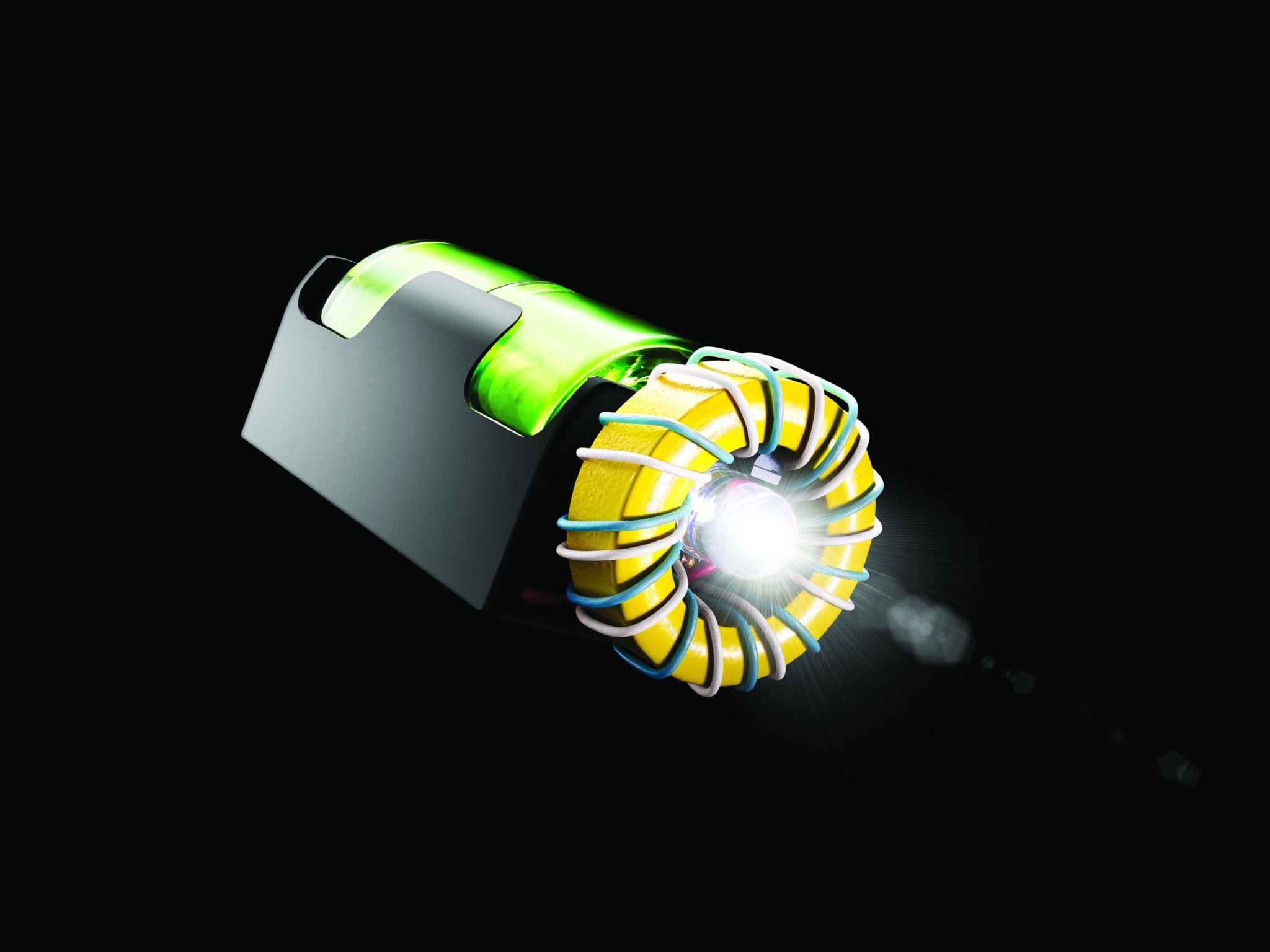
Don’t throw out that seemingly lifeless battery—it’s not dead yet. A brand-new alkaline battery cell has an electric potential of about 1.5 volts, which drops as the juice runs out. The voltage eventually becomes too low to power most devices, but there’s still energy trapped inside the battery—as much as 15 percent of the original charge. By wiring a circuit called a “joule thief,” you can tap the last of that power to light a white LED.

The circuit boosts the dwindling voltage but delivers it in pulses too rapid to see. As a result, the LED seems to shine constantly, even though it’s really powered less than half the time. Mount the joule thief on a D-size-battery holder, and it makes a handy flashlight, one that gives your old batteries new life.

This article originally appeared in the July 2015 issue of Popular Science, under the title “A Flashlight That Runs on Dead Batteries.”

Stats

  • Time: 2 hours
  • Cost: $30
  • Difficulty: Medium

Tools

  • Soldering iron
  • Wire strippers
  • Scissors
  • Double-stick foam tape
Joule Thief Schematic
Joule Thief Schematic Sean Michael Ragan

Materials

Instructions

Prepare The Battery Box

Prepare The Battery Box

The battery box has a negative end (with a spring contact and a black wire) and a positive end (with a red wire), plus small holes at all four corners. Route the wires out through the holes nearest the terminals to which they are attached. Loop the black wire across the negative end of the box and back in the opposite corner on the same end. Then run it down the long inside edge and out again on the positive end, opposite the red wire.
Attach The Switch

Attach The Switch

Use foam tape to mount the flashlight switch on the negative end of the box.
Solder The Switch

Solder The Switch

Cut the black wire right underneath the button, strip the ends, and solder them to the switch terminals.
Insert LED

Insert LED

Spread the leads on the LED slightly so they span three holes, instead of two, and install the light at the center of the protoboard, passing its leads through the holes.
Bend and solder LED leads

Bend and solder LED leads

Bend the LED leads as shown and solder them underneath the protoboard.
Install transistor

Install transistor

Refer to the transistor’s packaging (or look up the part number online) to identify its collector, base, and emitter leads. Install it on the protoboard right above the LED, and bend and solder its leads underneath to connect the emitter to the LED’s short lead, and the collector to the long lead. The image shows the placement of the transistor and resistor (resistor installation explained in Step 7).
Install resistor

Install resistor

Install the resistor on the protoboard right below the LED and solder its leads underneath. Bend the transistor’s base lead down between the LED leads, and solder it to the end of the resistor nearest the black battery wire. The transistor and resistor should be placed as shown in the image.
Prepare battery box leads

Prepare battery box leads

Cut the battery wires off about 1½ inches from the end of the box, then strip and tin their ends.
Install battery leads in protoboard

Install battery leads in protoboard

Install the battery box’s red wire on the protoboard immediately to the right of the LED, and the black wire immediately to its left.
Solder battery leads

Solder battery leads

Bend and solder the battery box’s black lead underneath the protoboard to connect with the LED’s short lead.
Insert wires

Insert wires

Cut two 20-inch lengths of wire, and strip and tin one end of each. Connect them to the protoboard: one to the red battery lead (the hole immediately below) and the other to the transistor collector (the hole immediately to the right).
Solder toroid wires

Solder toroid wires

Solder the wires in place. These wires will hold the toroid transformer core to the protoboard. From this point on, they will be “toroid wires.”
Thread wires through toroid

Thread wires through toroid

Pass the free ends of the wires through the hole in the toroid. Center the toroid over the protoboard, flush against the top, with the LED and other components inside.
Sew the first toroid wire

Sew the first toroid wire

Use the toroid wire attached to the transistor collector to “sew” the toroid to the protoboard: Thread the wire through every other hole around the board’s edge until you’ve made a full circle.
Sew the second toroid wire

Sew the second toroid wire

Repeat with the remaining toroid wire, the one attached to the red battery lead: Sew through the holes you skipped in Step 14. Do not cross the wires.
Thread the toroid wires through the board

Thread the toroid wires through the board

Thread the ends of both toroid wires through the protoboard. The first toroid wire (the one already attached to the transistor collector) should come through next to the red battery lead, and the second (the one already attached to the red battery lead) should be next to the free end of the resistor. Note their positions as shown in the photo.
Solder toroid wires to board

Solder toroid wires to board

Solder the first toroid wire to the red battery lead, and the second to the resistor.
Test the circuit

Test the circuit

Test the circuit by installing a battery in the holder and pushing the button.
Attach foam tape

Attach foam tape

Once you’re sure it works, snip off any excess leads, cover the board bottom with foam tape, and stick it to the positive end of the battery box.
Complete

Complete

The joule thief flashlight is now ready to use!