This story has been updated. It was originally featured in the April 2008 issue of Popular Science magazine and involves outdated technologies and services. For current advice, check out our regularly updated stories about how to set phone reminders for anything and the best note-taking apps for your phone.
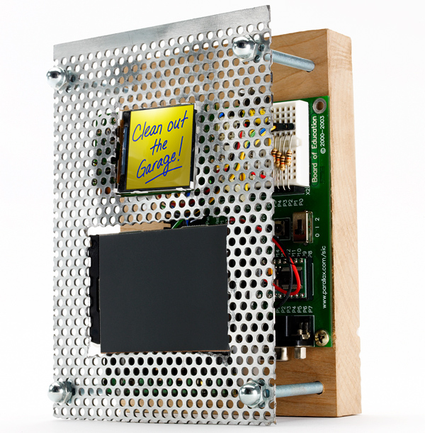
“Pick up milk.” “Feed dog.” “Finish homemade nuclear sub.” Like many people, I can’t function without writing little reminders to myself. But using one paper sticky note after another causes a lot of clutter and can be pretty wasteful. Instead, assemble a bunch of surplus parts into a digital note system for your kitchen or office. Just write out your message with your fingertip on a computer trackpad, and it appears on an LCD screen.
When you’re done, press a button and the screen is erased. Add a rechargeable battery and an enclosure, and you have unlimited (and eco-friendly) note-making capability. The project does require some computer code to drive the LCD. If you can just remember that, you’ll be good to go.
Make a digital notepad

- Time: 7 hours
- Cost: $175
- Difficulty: easy | | | | | hard (Editor’s note: 5/5)
Parts
- LCD + carrier board (SparkFun Electronics #LCD-00569 + #LCD-00600; $19.95 + $18.95)
- Trackpad (Electronic Goldmine #G1283; $1)
- Microcontroller (Parallax #28803; $99.95)
- PAK-XI mouse coprocessor (AWC #PAK11; $23.49)
- 3.3-volt voltage regulator (SparkFun Electronics #COM-00526; 1.95)
- 10mF electrolytic capacitor (SparkFun Electronics #COM-00523; $0.45)
- 4 (10K) resistors (RadioShack #271-1335; $0.99)
- 9-volt battery (available locally, $3)
- Hookup wire (RadioShack #278-1224; $5.99)
Instructions
1. Solder wires to the trackpad’s PS/2 connector. Connect them to the mouse coprocessor, which translates finger movements on the trackpad. Connect the coprocessor to the microcontroller so the program code can generate an image on the LCD screen.
- Note: A BASIC Stamp BS2 microcontroller is way too slow for adequately driving this project. The microcontroller used in this project was salvaged from an old Parallax Boe-Bot robot kit. Better performance could be obtained from AVR or PIC microcontrollers. In retrospect, I wouldn’t even consider using a BASIC Stamp for this project. If you do, you’ll be disappointed. Therefore, please consider this PBASIC code as a “starting point” for building a better digital notepad.
2. Follow the data sheet instructions on sparkfun.com to attach the voltage regulator and electrolytic capacitor to the screen. This adapts the screen’s power to the right level.
3. Plug the screen into the carrier board. Solder resistors to the board, and connect them to the microcontroller. Power the board by connecting pins to the voltage regulator.
4. Download our code for the screen at popsci.com or, if you substitute other components, from sparkfun.com.
5. Install a 9-volt battery. Program the microcontroller with the code from your PC. Test the device’s operation, put it in a custom-built box, and forget about those sticky notes.