Hacking the Esquire e-ink cover: a how-to
Bend an electronic magazine cover to your will.
As we mentioned in our earlier post on the Esquire e-ink cover, we have uncovered some additional details regarding the operation of this interesting e-ink evaluation board set. There are two eight-stage shift-and-store bus registers (HEF4094BT) that drive each of the two e-ink panels. The PIC12F629 controls the state of the HEF4094BT outputs: positive voltage, negative voltage, high impedance off, and shift register stage.
Please download these datasheets for more information about these two ICs:
- HEF4094BT datasheet
- PIC12F629 datasheet
You can also examine the content of the hex file that is programmed on the PIC12F629. You will need these products to read the hex file:
- PICkit 2 (#DV164120) datasheet
- Mouser (#579-DV164120; $49.99)
- Right-angle six-pin header Molex 0.100 K.K. connector (Mouser #538-22-28-8060; $0.43)
- Jumper wires, male (SparkFun Electronics #PRT-08431; $3.95)
- Jumper wires, female (SparkFun Electronics #PRT-08430; $3.95)
- Microchip MPLAB IDE #SW007002
Instructions
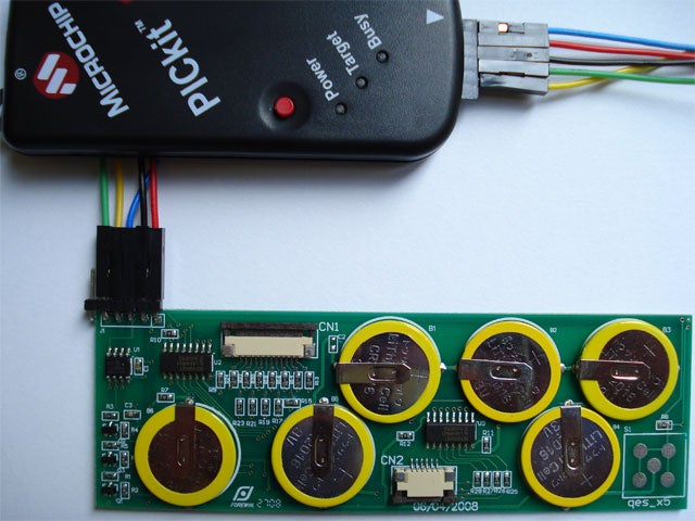
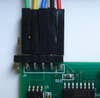
1. Solder the six-pin header to jumper J1 on the e-ink PCB. There are only five holes on the PCB for this header. Therefore, leave the extra sixth pin unsoldered off to the side of the PCB.
2. Attach the male and female jumpers together.
3. Insert five male jumpers into the ICSP connector on the PICkit 2 programmer. Route the female jumpers to the six-pin J1 header on the e-ink PCB. Use this chart for connecting the jumpers:
| J1 pin | Signal | ICSP pin |
| 1 | VDD | 2 |
| 2 | GND | 3 |
| 3 | Vpp | 1 |
| 4 | PGC | 5 |
| 5 | PGD | 4 |
| nc | Aux | 6 |
4. Connect the PICkit 2 to the USB port of a PC and start the PICkit software.
5. Click the Read Device + Export Hex File button. Save the hex file and exit the PICkit 2 app.
6. Start the Microchip MPLAB IDE and import the hex file that you saved in Step 5.
7. In the View menu, click on Program Memory. Your hex file will be disassembled and can be saved as a text file.
If you come up with any additional information regarding the Esquire e-ink cover, please post your findings in the comments section.