How to Build a Homemade Clapper to Adjust the Lights and Set the Mood
A sound-activated device that gives you more freedom than any store-bought clapper could wish for

One night, I was trying to draw a circuit on a chalkboard, but it became too dark to see. The next day I bought a new lamp, only to find that the board gave off too much glare. I needed a light I could easily adjust. I could have just installed a dimmer, but where’s the fun in that? As an engineer, I like to do projects that use a little electronics, a bit of mechanics and some software.
My friends and I had been talking about those old ’80s commercials for the Clapper, and it occurred to me that I could make a circuit that would dim the lights when I clapped my hands. The one I made is relatively inexpensive and a lot more functional than the original—it’s even got a Party mode that can pulse the light along with the beats of the music from my stereo.
THE LAMP
Pretty much any lamp will do, but a DC-powered LED one works best. Direct-current lamps run at around 12 volts, one tenth the power of regular AC lights, which also require different circuitry and carry the risk of a nasty shock.
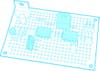
Close-Up on the Clapper Circuit
THE CIRCUIT BOARD
- A Darlington transistor manages brightness by switching the light off and on an imperceptible 40,000 times a second. The longer the “on” duration, the brighter it looks.
- An Electret condenser microphone, like the one in a cellphone, picks up the claps you intend—and the clangs, bangs and crashes you don’t. Note: You’ll need to ground the mic’s negative lead and connect the positive one to the operational amplifier input. If the leads aren’t labeled (+) and (–), check the product manual to see which one is which.
- The sound is amplified up to 100 times in the first stage of the op-amp, filtered to weed out highfrequency noises like a vacuum cleaner, and sent to the comparator stage, which distinguishes claps from non-claps by comparing the volume and pitch with a preset threshold.
- The wheel on the potentiometer controls the gain, or amount of amplification. Turn it down if the device is too sensitive.
- The signal moves from the op-amp to the microcontroller, the brains that run the clapper software. Once a clap is registered, the microcontroller listens for its next cue. A second clap within 1.2 seconds toggles the lamp on or off. Three claps start the lamp ramping up to maximum brightness and then back down to its dimmest point, until a fourth clap locks the light level in place. Four consecutive claps puts the device in Party mode, modulating the lamp’s brightness to the beats from your speakers. (To stop Party mode, you’ll need to flip a switch on the circuit board or the wall switch.)
THE PROGRAMMER
Download WinAVR for Windows or AVRDude for Mac, both of which are free, to get the clapper software from your computer to the programmer, which sends it to the microcontroller via a six-pin ISP connector.
Time: 5 hours
Cost: $50
Difficulty: 3 out of 5
For a full list of illustrated instructions, click through to the next page.
Instructions
_This is a revised hardware and software version of the original Clever Clapper Chalkboard Lights, which can be seen here.
In this version of the Clever Clapper:
- If you clap two times, the lamp will toggle its output on or off
- If you clap three times, the lamp will fade up and down until you clap a fourth time to stop it. Once it stops that brightness level is stored and restored for subsequent on and off cycles. This mode will also stop fading after one minute of operation and not hearing that fourth exit clap
- If you clap four times, the lamp will enter “party mode,” where the light output is modulated by the beat of music coming from a nearby radio of other sound source. The only way to exit this mode is to press the push-button switch on the circuit board or reboot the whole system.
You will need:
- A soldering iron and solder
- Diagonal cutters (or some method of cutting component leads and wire)
- Wire stripper
- Hookup wire
- Some proto board. I use a lot of RadioShack #276-150
- A multimeter with DC voltage and resistance measurement capability
- The software, which can be found here
- The bill of materials (BOM), which you can download [here](https://www.popsci.com/files/BOM_Clever/ Clapper v2.0.xlsx_.zip)
- And, optionally, the schematics, which are here
In addition to the usual electrical tools you will need an AVR In System Programmer (AVR ISP). I use the ATAVRISP2.
You will also need a DC lamp to connect your circuit to. Pick a lamp that is somewhere around 12VDC. Anything from about 9VDC to 18VDC should work fine with this circuit. This circuit is not capable of switching Alternating Current (AC).
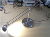
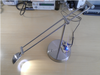
Lamp for Clapper
I picked up an LED Desk Lamp from Target. Above is a picture of the lamp I bought and below is the wall power adapter showing its specifications (350 mA at 12 VDC).
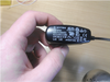
Power Adapter for Clapper
I made the Bill of Materials (BOM_Clever Clapper v2.0.ods) so that I could order all of the parts from one distributor. I included the part numbers for mouser.com, but you can order from wherever you like.
In addition, you will need a circuit board to solder all of those components to. I used a RadioShack #276-150 (picture below).
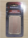
Circuit Board for Clapper
To build the circuit using point-to-point wiring on some proto board open up the Eagle and/or Fritzing schematics. (The Fritzing pictorial schematic is useful for showing how to connect your circuit board to the DC lamp.)
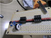
It took me about three hours, working at a very relaxed pace, to put the circuit together. I started with placing some IC sockets for the LM385 and ATTiny85 Ic’s. This is an optional step, but I highly recommend the use of IC sockets; they pay for themselves the first time you smoke a chip (or think you did and want to check).
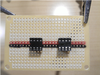
IC Sockets for Clapper
Here you can see how I bend the appropriate pins on the IC sockets to make the power and ground connections. Little things like that can save a lot of space on densely populated protoboard.
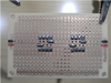
Protoboard for Clapper
Continuing construction I discovered that the electret microphone does not have markings on it to show which connection is positive and which is negative. I downloaded the datasheet for the part and discovered that the pinout is as shown in the picture below. The circuit will not work if the electret mic is installed backwards.
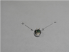
Electret Microphone for Clapper
As you continue adding parts, trim off the component leads from the back side with your diagonal cutters. I save these cutoff bits and bend them up for jumper wires later during assembly.
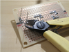
Potentiometer Installation for Clapper
Here we are installing the audio sensitivity potentiometer (pot). This adjusts the gain of the amplifier half of the op amp. Adjusting this will control how sensitive your circuit is to your claps. If you have it set too high it could potentially turn on and off unintentionally.
Potentiometer for Clapper
When you install the pushbutton switch, be careful with the orientation. Tactile switches generally switch “across” the line molded into the bottom (see photo). If the switch is installed in the incorrect orientation, the circuit will not respond to button presses.
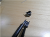
Push-Button Switch for Clapper
Next, cut off the wall adapter power supply. Check the polarity with your multimeter and wire it back up, including your completed Clever Clapper v2.0 circuit board using the Fritzing schematic from the download as guidance.
Here is a top and bottom picture of the completed clever clapper, including connections to the lamp and power supply.
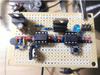
Completed Board from the Top for Clapper
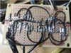
Completed Board from the Bottom for Clapper
After you check all of the electrical connections you made, plug in your lamp and your programmer. My programmer displays a green status light, which means that my ISP connections are wired correctly.
You will need some software on your computer to tell the programmer (ATAVRISP2) what to program. There are several ways to accomplish this. In Windows, use AVRDude to upload the *.hex file through the programmer to the ATTiny85 on the circuit board.
1: Install WinAvr from here.
2: From the software zip archive you downloaded above (or right here), find the file “clever_clapper_v2.0_main.hex” located in the and copy it to your root (C:).
3:Open a command prompt by typing “cmd” (without the quotes) at the run prompt.
4: At the command prompt change to the directory where you have the above mentioned *.hex file, C: in my case, and enter the following and hit enter.
avrdude -c avrispmkII -P usb -p attiny85 -U flash:w:clever_clapper_v2.0_main.hex
(If you use a different programmer you will have to let AVRDude know that by changing the -c switch. You can get all of the options for AVRDude by just typing ” avrdude ” at the command prompt.)
Your output should look like this:
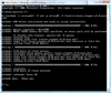
Programming Screen for Clapper
(If you are familiar with programming AVR’s the entire source code is also included in the Zip file you downloaded above.)
Here is a photo of the finished product. (Shown with optional LED indicator)
Finished Product for Clapper