Make a guess game
No microcontroller, no programming; just a handful of stock ICs—see if you can “guess” what comes next.
OK, guess a number between zero and 15. Wrong! Guess, again. No, I’m not the Amazing Kreskin, I’m just vying for numerical precognitive prediction superiority versus a formidable 74LS193/74LS85 tag team foe. Oh, sure, some of you might call it a game, but this project can be an amazing demonstration of just how much fun you can get from stock ICs.
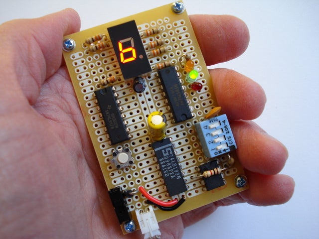
Derived from a Forrest M. Mims, III project, our Make a Guess game adds a seven-segment LED display for helping you visualize your numerical guess. Here’s how it works:
After you install your alkaline batteries and flick the power switch (S1), you press the button (S2) for sending a pulsing signal from the timer (NE555) to the “up” counting input of the 4-bit up-down counter (74LS193). This input triggers the 74LS193 into a counting mode where it counts upward between zero and 15, and then recycles until you release the button (S2). The resulting number is “memorized” and sent to the 4-bit magnitude comparator (74LS85). Now the 74LS85 “waits” for your “guess.”
You make your “guess” for the number that you think the 74LS193 sent to the 74LS85. This guess is entered into the 74LS85 with the four switches on the DIP switch (DIP-4POS). You can make a guess for any number between zero and 15 with this DIP switch. The switches represent these numbers:
- Switch 1 = 1
- Switch 2 = 2
- Switch 3 = 4
- Switch 4 = 8
- All switches = 15
- No switches = 0
The 74LS85 takes your entered number “guess” and compares it to the number supplied by the 74LS193. If the two numbers are equal to each other, a green LED will illuminate. If your guess is too low, an amber LED will light, and if your entered guess is too high, a red LED will light up.
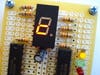
Also, your selected number “guess” is shown on the seven-segment LED display. This display is controlled by the BCD-to-7 segment decoder/driver IC (74LS47).
When your entered number guess matches the 74LS193 number, you’re a winner. Then you can press the button (S2) again and play another round of Make a Guess.
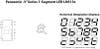
If you’re a sharp-eyed reader, you may be wondering how a seven-segment LED display can “show” the two-digit numbers 10 through 15. A set of rather bizarre displays are sent to the LED by the controlling 74LS47. These values are shown in the following illustration.
No advanced programming nor microcontroller will be used in this game. Relying solely on wire, a handful of digital transistor-transistor logic/standard logic (TTL/LS) integrated circuits (ICs), a timer, and battery pack, this game will give you hours of enjoyment. But the fun isn’t just inside the game. It’s building the game!
Yes, the real challenge is in point-to-point wiring. Using careful planning and tight IC placement you should be able to assemble this entire project on a single RadioShack multipurpose PC board (e.g., #276-150; $1.99).
Now to be completely honest with you, our prototype did not work properly. While we’re pretty sure the schematic is correct, our circuit problem was eventually traced to a faulty DIP switch. In fact, switch No. 2 of the DIP switch was internally shorted to the other switches creating a whole host of erroneous number “guesses.” Our bad.
Your next challenge, spoon bending 101.
Stats
- Time: 5 hours
- Cost: $19.19 (Prorated for number of components used in this project.)
- Difficulty: moderate
Parts
- 1K resistor (Electronic Goldmine #G455R; $3.50/100)
- 47K resistor (Electronic Goldmine #G489R; $3.50/100)
- 270 resistor (Electronic Goldmine #G442R; $3.50/100)
- (7) 330 resistors (Electronic Goldmine #G444R; $3.50/100)
- 10µF electrolytic capacitor (Electronic Goldmine #G13646; $1.00/10)
- 0.1µF electrolytic capacitor (Electronic Goldmine #G6089; $1.00/10)
- 0.1µF capacitor (All Electronics #104D50; $1.00/10)
- 1N4001 diode (All Electronics #1N4001; $1.00/15)
- Yellow LED (Electronic Goldmine #G5305; $1.00/12)
- Green LED (Electronic Goldmine #G13859; $1.00/20)
- Red LED (Electronic Goldmine #G1011; $1.00/9)
- Orange common anode seven-segment LED Panasonic LN513OA is no longer available; try this one instead: (Mouser #526-NTE3053; $3.54)
- SPST four-position DIP switch (DigiKey #CT2064-ND; $.59)
- SPST Omron B3F momentary switch (SparkFun Electronics #COM-00097; $0.35)
- 74LS47 (DigiKey #296-3712-5-ND; $1.44)
- 74LS85 (Electronic Goldmine #G4900A; $.35)
- 74LS193 (Electronic Goldmine #G4936A; $.59)
- NE555 (Electronic Goldmine #G32128; $.39)
- Power switch (SparkFun Electronics #COM-00102; $1.50)
- Battery holder (DigiKey #BH24AAW-ND; $0.90)
- Hookup wire (RadioShack #278-1224; $6.59)
Instructions
1. Download our resource archive for the Make a Guess game project.
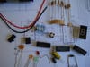
2. Lay out all of the ICs, switches, LEDs, resistors, and capacitors on the board. Make sure none of the components touch each other and that none of the board’s solder pads accidentally bridge any adjacent connections.
3. Follow the schematic carefully. Use your hookup wire for making all of the component connections.
4. Connect the red and black wires from the battery pack to the power supply (5V) and ground (GND) of the power switch (S1) and the circuit’s GND bus, respectively.
5. Check the voltage from the battery pack with a multimeter, it should register 6VDC. Now flick the power switch (S1) and read the voltage on all of the ICs. This value should be around 5VDC. If an IC doesn’t have the proper voltage, immediately disconnect the battery pack and recheck all of your wiring.
Once you’ve got a properly working game, give it a whirl and see if you can quickly guess the number generated by the 74LS193 “mentalist.”