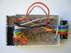
Holiday project: Dot-matrix LED ornament
Just a simple light-up ornament.

Are you looking for a unique decoration for a special Christmas present? Then consider building this inexpensive ornament for adorning your next gift. You can easily hard-wire the 5-by-7 dot-matrix LED into just about any visual configuration that will fit within a grid of 35 green/red pixels. We have presented you with two templates for wiring a Christmas tree configuration. Refer to the BG Micro datasheet for the relevant wiring connections. For the more versatile gift box accoutrement, however, this simple programmable dot-matrix LED uses DIP switches for illuminating rows/columns of pixels. Granted, this project isn’t as flexible as individually programmable pixels, but it should help you get started with building your own more complex dot-matrix LED ornament.
Stats
- Time: 5 hours
- Cost: $4.64
- Difficulty: moderate
Parts
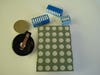
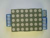
- 5-by-7 LED dot matrix (BG Micro; $1.49)
- 10-conductor rainbow ribbon cable (All Electronics; $1.75)
- Coin cell battery holder (BG Micro; $0.75)
- CR2032 battery (BG Micro; $0.65)
- (Optional) 2 (8-position) DIP switches (RadioShack; $2.79)
- (Optional) 4-position DIP switch (BG Micro; $0.40)
Instructions
1. Bond the DIP switches to the sides of the 5-by-7 dot-matrix LED. In our example, one 8-position DIP switch is used for controlling the anode rows, while a second 8-position DIP switch and a 4-position DIP switch are used for toggling the cathode columns on and off.
2. Solder all of the OFF position pins of each DIP switch together. This will form a run—or bus—of connected pins on each switch.
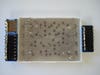
3. Cut a length of ribbon wire to reach from the single 8-position DIP switch to all of the appropriate anode pins on the dot-matrix LED. Solder all matching anode row pins together (e.g., anode row 1a soldered to anode row 1b; pins “a” are red LEDs and pins “b” are green LEDs). Connect the ON pin for position 1 on the DIP switch to anode row pin 1 combination. Similarly, connect the position 2 pin of the DIP switch to anode row pin 2 combination. Finish soldering the remaining 6 pins of the DIP switch to their corresponding anode row combinations. Please notice in the datasheet that there are two pin sets for anode row 4. Therefore, solder position 8, on the DIP switch, to the second anode row combination for pin 4 (e.g., pins 25 and 26).
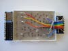
4. Solder position 1 of the second 8-position DIP switch to cathode column 1a. Now solder position 2 of the same DIP switch to cathode column 1b. Finish the remaining 6 positions of the DIP switch. Continue soldering the remaining dot-matrix LED cathode column pins to the 4-position DIP switch. Notice that there are two cathode column pin sets for column 3 (e.g., pins 7 and 8 and pins 21 and 22).
5. Connect the battery holder’s positive (+) terminal to the anode run or bus on the single 8-position DIP switch. Connect the negative (-) terminal of the battery holder to the cathode bus on the second 8-position DIP switch and the 4-position DIP switch.
6. Flip the DIP switches for illuminating LED rows and columns.