The Shocking Truth: How To Make High-Voltage Sparks
I’ve always thought it would be funny to build scale-size exploding grain silos for a model train layout. I’ve also...
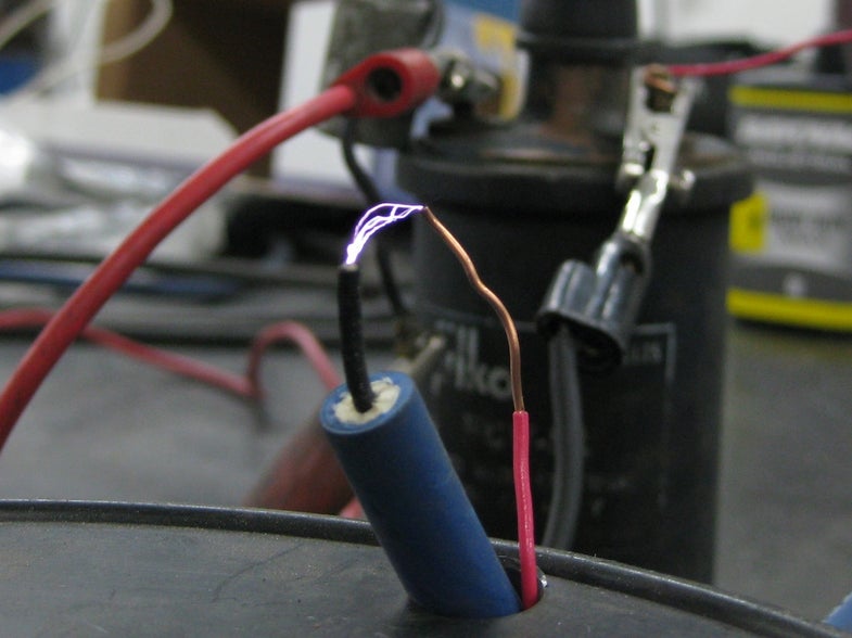
Spark Plug Doing Its Thing
I’ve always thought it would be funny to build scale-size exploding grain silos for a model train layout. I’ve also had problems recently with pilot flames blowing out in some of our larger blow-something-flammable-through-something-on-fire projects. Both of these things made clear to me that I needed a good source of high-voltage sparks. So I built a buzz coil, a project derived from the ignition on a Model T that you can toss together to satisfy all your sparking needs with a just a few common automotive parts.
The basic transformer theory is laid out in my previous posts about Variacs and Automotive Ignition Coils. To understand the buzz coil, the key point is that a changing current generates a collapsing magnetic field in a transformer. That collapsing magnetic field induces a voltage in the secondary winding of the transformer. In the case of an automotive ignition coil, we’re talking about very high voltage.
That’s why the basic design for the buzz coil is lifted from the ignition system of antique engines, like the ones in a Model T Ford. More recently, the design was tossed around by these guys on an Old Marine Engine forum. I decided to build their buzz coil.
Ingredients:
- 5 pin automotive relay. Bosch p/n 0 332 209 150. ~$5.
- Some spade connectors and possibly a relay socket.
- Ignition Coil. Use whatever you have around. If you need to buy one, a mid 60’s Ford pickup truck coil works fine. Napa p/n IC10SB. $16.
- Ignition Condenser. Use what you have lying around, or grab a 60’s Ford item. Napa p/n FA82SB. $5
- Ignition wire and ends – one spark plug cap and one coil cap. If you don’t have anything lying around, cruise to the local auto parts store and see what they can do for you. Any auto parts store worth its salt will have a spool of spark plug wire and some fittings.
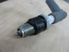
- Spark Plug. Any spark plug will do.
- 12V Battery. Any battery will work. For a light, compact, sealed battery, look at Deka p/n ETX9. It is 6″ x 3 7/16″ x 4 3/16″ and weighs 6.3 lbs.
- A momentary toggle switch or push button
How it Works:
Spark Plug Doing Its Thing
A relay is an electrically operated electromechanical switch. It consists of a conductive arm (or arms) that make and break electrical connections as they are moved from one position to another by an internal electromagnet coil. In the case of the relay used for this project, one arm can complete either of two possible circuits. A relatively low current circuit is used to switch this relay on and off, while the switched circuits can handle relatively high currents. A relay like this is used to control the headlights in your car, allowing that high-current load to be switched by a low current switch in your dash cluster.
Things like momentary switches and relays use terminology like Normally Open (NO) and Normally Closed (NC). Normally Open means that the electrical connection is not made in the default state; no current will flow through those terminals when the switch or relay is in its idle state. Normally Closed means the opposite; current flows unless the relay is activated.
In this buzz coil, we make use of the fact that the Bosch 5 pin relay has both NO and NC terminals. (The more common 4-pin relay has only a NO terminal.)
Our relay is wired such that power to the relay’s coil is connected through the Normally Closed circuit. This means that as soon as power is connected, two things happen: Power goes to the positive terminal of the ignition coil, which is also connected to the NC terminal, and the relay is activated. The relay, now activated, moves its internal arm to make the NO connection, thereby breaking the NC connection. Breaking that connection disconnects the power to the relay’s coil. When the relay’s coil de-energizes, the spring loaded arm returns to its default position. In this position, the NC circuit is completed once again and through it, the battery power is connected back to the positive terminal of the ignition coil and the relay’s coil is re-energized. For as long as power is connected (or until the relay catches fire), the relay oscillates between these two states as fast as it’s mechanical components will allow. This rapid oscillation means that the 12V power from the battery is being connected to and then disconnected from the positive terminal of the ignition coil over and over again, very quickly. The negative terminal of the ignition coil is connected to ground. Connected in this way, the ignition coil experiences a rapidly changing current through it’s primary, which results in a high voltage being induced in the secondary winding. That secondary is connected to the spark plug.
As the relay turns power on and off to the ignition coil over and over again very quickly, the changing current turns into a series of high voltage spikes at the spark plug. It is very similar to what happens in a points-style automotive ignition system.
One seemingly extra part here is the condenser. The condenser is connected across the Normally Closed terminals of the relay just as it is connected across the points in an automotive ignition system. It helps to prevent sparking across the points as they open (inductors like the winding of the ignition coil tend to resist rapidly changing voltages and don’t take kindly to the points opening).
How to Build It:
Spark Plug Doing Its Thing
Putting this Buzz Coil together is as simple as following the wiring schematic. If you’re using a socket for the relay, make the connections to the socket’s pigtail. Otherwise, crimp on spade connectors can be pushed directly onto the relay’s terminals, as I did in my build. How exactly you make your wiring connections will depend on the physical configuration in which you plan to use the coil. If you are going for a compact setup, as I was, you may find it easiest to mount the condenser directly on the coil. I had to enlarge the mounting hole in the condenser slightly to fit onto the stud on top of the coil. Your mileage may vary.
Connect the ground terminal of the battery to the housing (the threaded part at the base) of the spark plug to complete the circuit.
Follow the schematic below. If you look closely at the relay in the schematic, you’ll see that the terminals are numbered. While the relay will not physically look like the one in this schematic, you will see those same numbers next to pins on the bottom of your relay.
Spark Plug Doing Its Thing
Spark Plug Doing Its Thing
Once you have a buzz coil, you have all kinds of great options for ignition. A word of caution applies. You will be dealing with very high voltages, and if you cause yourself to be part of the ground path, it will at the very least hurt like the dickens, as my father says. And at worst, well, it could be a lot worse. Be very careful to ensure that there is a directly ground path from the housing of the spark plug back to the negative terminal of the battery, and that you and nothing you are touching are part of the ground path. It might be wise to wear non-conductive gloves while you are playing with this.
Ignoring those words of wisdom, here is what I did with mine:
Dispatch From The TE Labs: The Buzz Coil from Vin Marshall on Vimeo.
Vin attempts to simulate a grain silo explosion with flour and a high voltage spark generator. He fails and has to resort to carburetor clearner.