The Dissection: A Home Electric Meter
A peek inside the simple gears and complicated math that make up one of the coolest devices in your house
You remember calculus, right? In a time before mechanized computing was performed by computers, complex (or sometimes just clever) machines were used to automate calculations. One example that has always impressed and fascinated me is the wheel-and-disk integrator, a simple machine capable of solving the calculus equations you labored over in high school without breaking a sweat. While this concept was used most impressively in Vannevar Bush’s differential analyzer, an analog computer built in 1931, the chances are good that you’ve seen one in a more mundane application around your house: the power meter. Click on the photo gallery to see inside one and how it works, and follow the jump for more in-depth electro-geekery.
The mechanical style of electric meter makes use of the wheel-and-disk integrator [1] concept to calculate the amount of energy used by a home or business. Recall from your basic electricity concepts Ohm’s Law, which tells us that P = VI; that is, the instantaneous Power (P) passing through a circuit element (such as the entire electric load of a house) at any given moment is equal to the Voltage (V) potential across that element multiplied by the Current (I) passing through that element [2]. Now, were we to represent that quantity of Power in some way and then to take the sum of each instantaneous power value over a period of time, we would have the amount of power used during that period of time. This is known as Energy, and energy consumption is what is measured by a power meter.
Here is how the power meter does it:
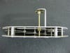
1. Current passes through the meter on the way to the circuits inside the house (and again on the way back out). As the current flows through the meter, it flows through two large copper conductors that are wrapped around a magnet. Because we are dealing with AC electricity (alternating current), the current flowing through the those conductors is changing and therefore, with the help of that magnet, creates a changing magnetic field proportional to the amount of current flowing.
2. Voltage across the meter (and therefore across the entire house’s circuitry) is also measured. Another coil—essentially half of a transformer—sets up another changing magnetic field which represents the voltage.
3. A principle called superposition applies to magnetic fields, which, in simple terms, means that if there are two things creating a magnetic field in the same area, the resulting magnetic field in that area will be the sum [3] of those fields. As stated above, we have a field that has been created proportional to the current flow, and we have another field that has been created proportional to the voltage. Since these magnetic fields both exist in the same space, superposition tells us that the resulting magnetic field is the sum of both of those fields. This magnetic field overlaps part of an aluminum wheel, which is the recognizable horizontal spinning wheel of a power meter.
4. A phenomenon known as an eddy current, which is beyond the scope of this post, causes that wheel to move in the presence of the changing magnetic field, even though the conductive wheel itself is not magnetic. All of the components involved are sized such that the magnitude of the magnetic field being produced by the sum of the Current and Voltage magnetic fields results in a speed of rotation in the wheel that’s proportional to the product of current and voltage. In other words, the big wheel is spinning at a rate proportional to the amount of power being consumed at any moment.
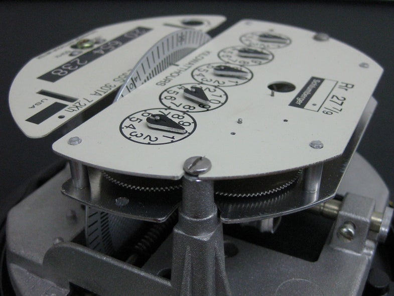
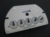
5. The rotation of that wheel, and the shaft which supports it, turns a system of gears. The gears and their attached indicator wheels function as an accumulator; the total amount of power used is recorded because the instantaneous power used is continually being added to the running count. The system of gears is sized by factors of 10, which creates a multi-digit display in much the same way that an odometer works in a car. In the case of this meter, five significant digits are stored and represented by these geared counters.
In this way, instantaneous power consumption is continually translated into mechanical movement and accumulated, recording the amount of energy used.
[1] The wheel-and-disk mechaism used in the power meter is referred to as an integrator. Take a moment to peruse the wikipedia article on Integrals before continuing if you are not familiar with basic calculus concepts. In calculus, a finite integral is akin to the sum of the area under a continuous curve, or the limit of the sum of the f(x) values of all points on the curve as the interval between points approaches 0. Because the speed of the spinning wheel represents the f(x) value and the geared counter counts those rotations, the power meter calculates the area under a curve, or the finite integral. This concept was initially developed by J. H. Hermann, refined by James Maxwell, and refined again by James Thomson (older brother of William Thomson, aka Lord Kelvin). After adding the crucial innovation of a torque multiplier, allowing multiple stages of these wheel-and-disk integrators to be chained together, Vannevar Bush made impressive and practical use of the concept in his differential analyzer.
[2] Current is measured and talked about as passing through things. Voltage is measured as a difference between two points. So, we have current through a point and voltage at a point (relative to another point). Accordingly, we talk about current and voltage differently.
[3] The vector sum actually, since magnetic fields have directions as well as magnitudes.

Electric Meter
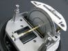
Electric Meter – The Spinning Wheel
Electric Meter – The Dials
Electric Meter – Counter Wheels (Top View)
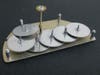
Electric Meter – Counter Wheels
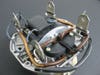
Electric Meter – Coils Installed
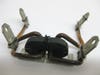
Electric Meter – Coils Liberated