How To Build A Soft Robot Hand
Use it to wave hello or flip the bird
In the field of soft robotics, engineers use squishy materials to make robots durable, flexible, and safer to operate around humans. Now intrepid DIYers can also bring life to squishy machines: Last September, Harvard University published an open-access Soft Robotics Toolkit online.
Some of the materials and skills Harvard recommends may be beyond the reach of a typical garage roboticist. But with a little ingenuity, you can substitute cheaper parts and simpler techniques. This project makes actuated “fingers” out of ribbed hose from a cheap foot pump, long thin balloons (the type you can twist and fold into animals), and other basic items. By attaching five fingers to a limb–in this case, a plastic gauntlet from a set of toy armor–you can form a robot hand.
Once you’ve assembled your appendage, it’s time for phase two of the project: building a fluidic control board. The Arduino brain controls and coordinates air valves to make the hand flash the peace sign, hang loose, or even flip the bird.
Stats
Time: 8 hours
Cost: $70 (hand), $400 (control board)
Difficulty: 5/5
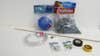
Materials
7/16-inch inner diameter ribbed hose
5/16-inch wood dowel
1/4-inch outer diameter vinyl tubing
Small hose clamps
Five 1/4-inch hose barbs x 1/4-inch male threaded adapters
Five 1/4-inch hose barbs x 1/4-inch female threaded adapters
Electrical tape
Yellow Teflon thread tape
Several long balloons (type 350Q)
1-inch x 6-inch board or other support
Fluidic control board
Robot Hand Instructions
1. Insert the 5/16-inch dowel into the ribbed hose to hold it straight. Use the center punch to carefully punch holes between each rib in a line along the seam of the hose. Flip the hose over and repeat along other seam.
2. Use the drill press to drill a hole at each center-punched location between the hose ribs, leaving the dowel in place to provide support. It is best to drill the holes on each side of the hose separately, rather than drill straight through. When you are done you should have a neat line of holes on each side of the ribbed hose. These holes will act as a stress relief and prevent the hose from splitting when it is flexed.
3. Remove the dowel and cut the hose into five 3-inch fingers with the utility knife. For each finger, use the utility knife to very carefully cut between each rib from the hole on one side to the hole on the other. Leave the first two ribs on each end uncut. Cut through one side of the hose only. It is critical that you do not nick the far side of the stress relief holes or you will reduce the reliability of the finger dramatically. Now the hose can flex in one direction more than in the opposite direction.
4. Insert another piece of dowel into one of the long balloons. Use it to gently feed the balloon into one of the fingers until the end of the balloon sticks out enough to grab it. Remove the dowel, and fold about 1/4-inch of the balloon tip over the rim of the hose. Secure it by wrapping a piece of electrical tape all the way around the tip of the finger.
5. Now feed the dowel back inside the finger from the non-taped end, but on the outside of the balloon. Insert it until it is just within two ribs of the tip of the finger. Fill the tip of the finger with hot glue, allow to cool, and then carefully remove the dowel.
6. Use electrical tape over the end of the finger, covering the hot-glued end. Another wrap of electrical tape over this will seal the end of the finger.
7. Cut the open end of the balloon away, leaving about an inch beyond the end of the finger. Stretch the open end of the balloon out and over the end of the finger.
8. Repeat steps 4 through 7 for each finger.
9. Use the yellow Teflon tape to wrap the threads on each of the male hose barbs. Thread each male hose barb onto each female hose barb and tighten firmly with the crescent wrenches. Then use more yellow Teflon tape and wrap each female hose barb several times around. The ends of these hose barbs should fit snugly into the open ends of each finger.
10. Use the small hose clamps to affix each finger onto the Teflon wrapped ends of the five hose barbs.
11. Now use hot glue to firmly attach each finger to the end of the 1×6-inch board (or other support) to form a hand. Finally, attach a length of 1/4-inch O.D. vinyl hose to the open hose barb on each finger.
12. Now the hand is complete–but it still needs a control system. Check out Harvard’s Soft Robotics Toolkit for inspiration, or just follow the instructions below.
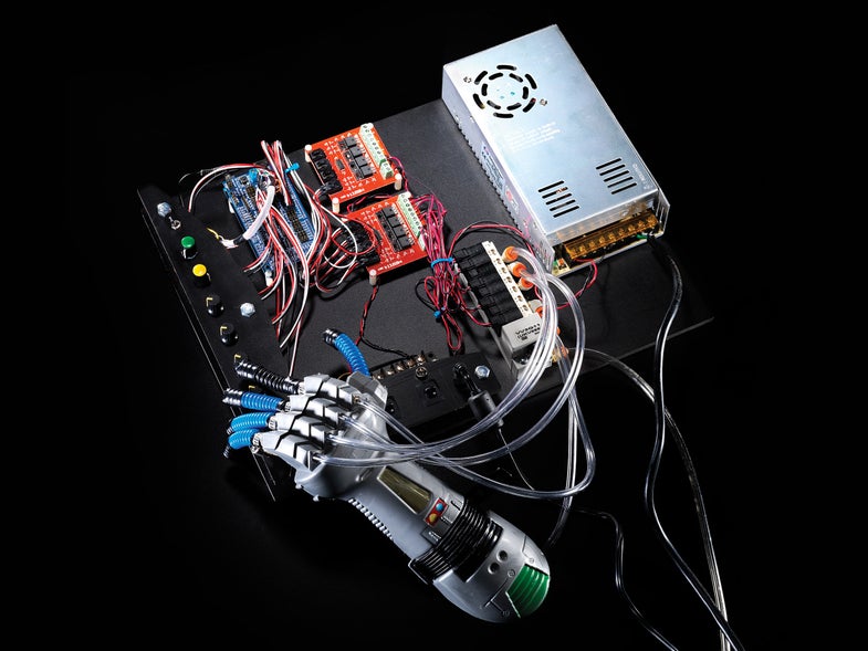
Building The Fluidic Control Board
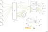
Fluidic Control Board Schematic
This is a complex project. Since your control board is a considerable investment in time and money, consider future expansion as you plan your build. For example, you may wish to buy an 8-port manifold and appropriate valves and fittings, so you can expand the board to control more actuators than then five you need for the robot hand project. Got questions about the project? Contact Andrew Terranova.
Control Board Materials
Air compressor with regulator
1/4-inch Sintra PVC board (12-inch x 24-inch)
12V 1A DC Power Supply with size “M” 2.1-mm x 5.5-mm coax connector
Panel-mount coax power jack, size “M” 2.1-mm x 5.5-mm
Coax power plug, size “M” 2.1-mm x 5.5-mm
Arduino Mega 2560 or compatible
Five SMC VQ110U-5M-M5 air valves (or similar: 24VDC, connector with lead wires)
One SMC VV3Q11-05 5-port manifold (or similar)
1/4-inch outer diameter vinyl tubing
Six 50-kilohm potentiometers (“pots”)
Seven 6-mm shaft potentiometer knobs
22 gauge stranded or pre-bonded wire (black, red, and yellow)
24 gauge multi-conductor cable or ribbon cable (13 conductors needed)
6-gang terminal block
Three single pole double throw toggle switches
Two 5-mm yellow LEDs
Two 5-mm LED mounts
560-ohm resistor
1.2-kilohm resistor
Twelve M 3-mm x 6-mm Phillips plastic PCB board fasteners
Twelve 21-mm x 6-mm PC board spacers
Five 1/4-inch 2-inch hex bolts
Ten 1/4-inch hex nuts
Two 10-32 1-inch bolts
Double sided foam tape
Shrink tubing
Wire zip ties (for cable management)
Control Board Tools
Table saw
Pencil
Center punch
Drill and drill bits (13/64″, 17/64″, others sizes based on component dimensions)
Metric tap M 3-mm x 0.5-mm, standard 10-32-inch tap (other sizes based on component dimensions)
Soldering iron and solder
Wire stripper
Flathead and Phillips screwdrivers
Adjustable wrench
Lighter (for shrink tubing)
Control Board Instructions
1. Lay out the control board. You can base your design on the photos, but adjust it to suit your own needs. It is convenient to have the power and controls near the edges where you can reach them. It is also convenient to have the Arduino Mega/Sensor Shield between the controls and the MOSFET power switches. The MOSFET modules should be close to the air valves/manifold. Power supplies can be placed wherever you like, but consider how power will be routed around the board.
2. Cut the Sintra board using a table saw to a size to fit your layout. 12 inches by 16 inches should do. This will be the base of the control board.
3. From the remaining Sintra board, cut one piece for mounting the controls (about 12 inches by 2¼ inches). Cut another piece for the power switches and indicators (about 2 inches by 6 inches). Cutting a curve on one side of each of these pieces lets you fit them more compactly on the base, and adds a touch of style.
4. Use a pencil and a center punch to mark holes on the two mounting boards for the 50-kilohm pots, switches, LEDs, power jack, and for the hex bolts that will mount the boards to the base.
5. Drill the holes in the mounting boards. It is possible to tap threads into Sintra board if you want to screw the pots directly into the board, rather than use nuts to hold them. Use one “sacrificial” pot as the tap, if you don’t have the proper size tap to cut the threads (this may damage the pot).
6. Use hex bolts and nuts to raise the two mounting boards above the base. Before you install any components in the mounting boards, line them up on top of the base where you want them. Using the holes you drilled for the hex mounting bolts as a guide, mark the base. Then drill 13/64-inch holes in the base and make threads using a 1/4-inch by 20 tap.
7. The Arduino Mega and the MOSFET switches should be mounted using M 3-mm x 6-mm Phillips plastic PCB board fasteners. Mark, drill, and tap holes to mount them and the other components. The 24V power supply may be mounted with double-sided foam tape. The air manifold can be mounted with two 10-32-inch bolts or with the foam tape.
8. Mount the 24V power supply, air manifold, MOSFET switches, Arduino Mega and Sensor Shield, and 6-gang terminal block to the base. The terminal block may be mounted with small self-tapping screws or with foam tape.
9. Mount all the pots, switches, LEDs, and the power jack to the two mounting boards, but don’t mount the boards to the base yet. You have some soldering to do first.
10. Follow the included schematic to wire the six pots, the 12-position switch, and the SPDT switch on the control mounting board. Connect the wires as shown to the Arduino Mega Sensor Shield.
11. Follow the included schematic to wire the 12V power jack, power switches, and LEDs for the power mounting board. Connect the wires as shown to the 6-gang terminal block. Wire the 24V power supply as shown, and connect the 12V power jack. Leave the power supplies unplugged from the AC wall socket for now.
12. Mount the control and power boards to the base board using 1/4-inch hex bolts and nuts. For each bolt, set one nut flush to the base board and another flush to the mounting board from underneath. This will hold the mounting board firmly.
13. Run power from the 6-gang terminal block to the Arduino Mega and MOFSET switches. Check the schematic for details.
14. Connect the digital out pins of the Arduino Mega Sensor Shield to the input channels of the MOSFET switches as shown in the schematic. Then wire the channel outputs of the MOSFET switches to five of the SMC air valves.
15. Connect the 1/4-inch outer diameter vinyl tubing from the five air valves to the robot hand. Connect more 1/4-inch tubing from the input of the air manifold to your air compressor. You should set the output of your compressor to about 20 pounds per square inch. You may need to adjust the pressure from the air compressor to slightly more or slightly less, but this is a good starting point.
16. Plug in the 12V and 24V power supplies. Turn on the 12V supply power switch only (for now).
17. Download the included software sketch example. Set up your Arduino programming software, connect to the Arduino Mega, and then compile and download the sketch to the Mega.
18. Now turn on the 24V power switch. With the function selector switch in one position, you should be able to control each finger with one of the five pots. Try adjusting the duty-cycle pot to different positions and see how it works. With the function selector switch in the other position, the 12-position switch will control the position or motion of the hand.
19. Behold the glory of your creation! Here’s our soft robot hand in action:
This article was originally published in the May 2015 issue of Popular Science, under the title “Wave Hello To A Soft Robot Hand.”